
Green Hydrogen: Solar-Driven Water-Splitting and Optimization
By: Bhushan Patel
It is evident that our current system of harnessing energy cannot continue indefinitely. Fossil fuels not only deplete without regenerating but they also produce harmful pollutants that contribute directly to global warming. This requires us to go beyond merely finding new sources of energy production; it requires us to find new sources of energy storage. Hydrogen is a strong contender as it has a high energy density rivaling that of gasoline, can be compressed and stored as a gas for uses such as onboard fuel for cars, only produces water and heat when combusted, and most importantly, it can be produced from water. [1] Electrolysis of water produces hydrogen by passing an electric current through an acidic or basic water medium that contains electrodes coated with catalysts which “split” water into H2 and O2. However, in practice this is much more complex and we must examine the different components of this process in order to see how they can be optimized individually and make electrolysis more efficient and commercially viable as a whole.
While the overall water electrolysis reaction is easy to understand, the underlying mechanisms can be much more complicated. For starters, there is more than one method by which electrolysis can be carried out, resulting in different types of electrolyzers. The two main types we will talk about are alkaline and proton exchange membrane (PEM) electrolyzers. While they have many differences, the key one is the use of different water electrolytes (alkaline vs acidic), which also results in different sequences of chemical reactions and effects of the catalysts employed. However, the oxygen evolution reaction (OER) and hydrogen evolution reaction (HER) still take place in both. Each one has its own unique advantages as well. Alkaline electrolyzers are cheaper, more stable in the long-term, and commercially mature (verified after contacting several manufacturers such as Teledyne, Hydrogenics, and Nel Hydrogen). [2] But PEM electrolyzers offer higher current densities, are more adaptable if connected to renewable energy sources, and produce purer hydrogen. [3]
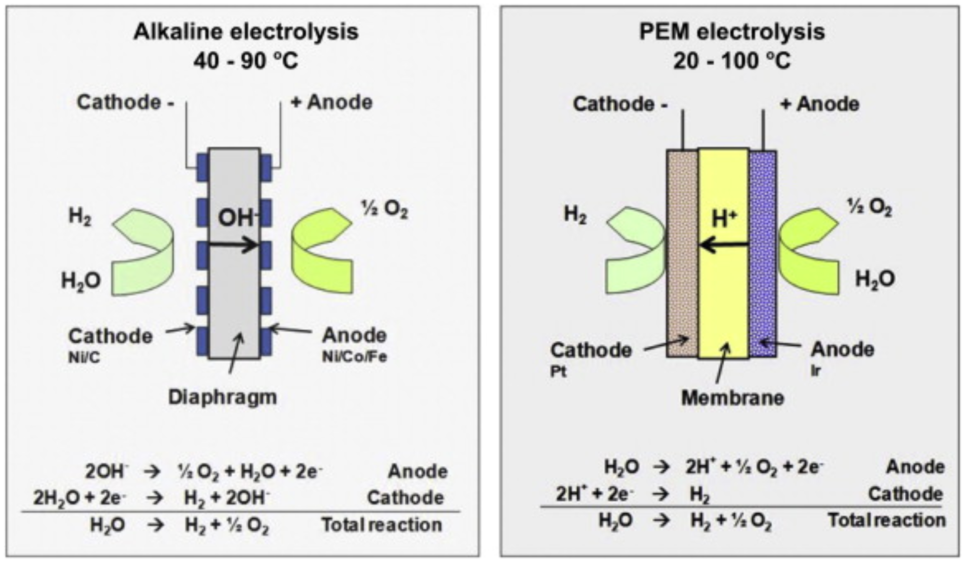
Figure 1: Alkaline VS PEM Electrolysis [3]
The harsh acidic environment of PEM electrolyzers means primarily PGMs (platinum group metals) can be used as catalysts, creating a cost bottleneck holding this technology back. On the other hand, even though alkaline electrolyzers can use cheaper, often nickel-based catalysts, they are not as electrochemically active as PGMs and therefore produce less hydrogen for a given amount of water. This creates a tradeoff between cost and hydrogen production efficiency and opens the avenue for catalyst optimization. A plethora of factors must be considered when creating these catalysts such as stability, efficiency, electrochemical surface area (ECSA), bifunctionality for both OER and HER, turnover frequency, self-healing properties, and much more. However, two characteristics are particularly helpful when comparing the catalyst performance: the overpotential and the Tafel slope. The overpotential is the extra voltage needed above the theoretical voltage of 1.23 V to perform electrolysis due to chemical inefficiencies, high activation energies, etc. [4] The Tafel slope represents how much the overpotential must be increased by to increase the rate of reaction by a factor of ten (measured in mV/dec). To illustrate the difficulty in optimizing a catalyst, let us consider a helical borophosphate catalyst reported in 2019, LiCoBPO. [5] This catalyst has an overpotential and a Tafel slope less than those of PGMs at a 10 mA/cm2 current density, in addition to exhibiting an exceptional stability of 2.5 months. Nevertheless, a single catalyst layer only produced about 100 mL of hydrogen a day, which was much lower than the production rate of PGMs. However, one could increase the number of layers used, but that would require much higher current overall and would be more energy-intensive. There is also a fundamental limit to how many layers can be stacked before the resistance becomes too high to be economically feasible. Alternatively, one could apply a higher current to a single layer but that would decrease the stability and require frequent catalyst replacement, which would be more expensive in the long run. This leads to a rabbit hole of tradeoffs which must all be accounted for, making the catalyst optimization process incredibly challenging.
Another difficulty lies in how this process is powered. While only electricity is required, it can come from any source. However, to make the whole process environmentally friendly, it must come from renewable sources, solar energy being especially promising. This raises further possibilities of how the catalyst and photovoltaic (PV) power source can be coupled and the three most common ways are photocatalyst (PC), photoelectrochemical cell (PEC), and photovoltaic-electrochemical cell (PV-EC). PC uses a catalyst that can directly absorb sunlight to power the reaction. While a very self-contained process, it has the lowest solar-to-fuel efficiency (SFE) of the three methods at around 5%. PEC uses a photoactive semiconductor electrode that directly interfaces with the electrolyte to produce hydrogen. While it has a higher efficiency than PC (~10%) and lower cost than PV-EC, it is not the most stable platform and changes to a single component requires taking the interaction of the whole cell into account. The last method is PV-EC that decouples the PV energy source (e.g., solar cell) and the actual electrode with the catalyst. While this decoupling enables individual optimization of the components and the highest efficiency (>30%), it is more expensive and there is a significant energy lost in the transfer due to the additional resistive losses of the wires. [6] This highlights how the optimization challenge of the catalyst material also plagues the energy source and coupling strategy.

Figure 2: PEC VS PV-EC coupling [7]
While it is easy to look at a source of energy or storage and try to determine its efficiency or efficacy right away from a single metric, the practical case highlighted above demonstrates the difficulty that tradeoffs pose. No single metric can capture all the attributes of a system; it is necessary instead to formulate a specific goal in each case and cater tradeoffs to achieve that, rather than try to chase a one-size-fits-all solution that is unilaterally “the best.” As more and more clean energy solutions continue to be discovered, however, there will inevitably be resource scarcity. This is why solar-driven electrolysis’ reliance on water and solar energy, some of the most abundant resources around, will cause it to remain competitive and crucial in the future.
References
[1] A. Li, Y. Sun, T. Yao, H. Han, “Earth‐Abundant Transition‐Metal‐Based Electrocatalysts for Water Electrolysis to Produce Renewable Hydrogen,” Chemistry Europe Journal, 2018, Volume 24, Issue 29, DOI: 10.1002/chem.201803749.
[2] United States, "Technology Brief: Analysis of Current-Day Commercial Electrolyzers", September, 2004, https://www.osti.gov/servlets/purl/15009551.
[3] Marcelo Carmo, David L. Fritz, Jürgen Mergel, Detlef Stolten, “A comprehensive review on PEM water electrolysis”, International Journal of Hydrogen Energy, Volume 38, Issue 12, 2013, Pages 4901-4934, DOI: 10.1016/j.ijhydene.2013.01.151.
[4] Paul Flowers, “Electrolysis.” Chemistry LibreTexts. Libretexts, July 14, 2020. https://chem.libretexts.org/Courses/Louisville_Collegiate_School/General_Chemistry/LibreTexts%2F%2FLouisville_Collegiate_School%2F%2FChapters%2F%2F17%3A_Electrochemistry/LibreTexts%2F%2FLouisville_Collegiate_School%2F%2FChapters%2F%2F17%3A_Electrochemistry%2F%2F17.7%3A_Electrolysis.
[5] Prashanth Menezes, Arindam Indra, Ivelina Zaharieva, Carsten Walter, Stefan Loos, Stefan Hoffmann, Robert Schlogl, Matthias Driess, “Helical cobalt borophosphates to master durable overall water-splitting,” Energy and Environmental Science, 2019 Issue 3, 17 October 2018, Pages 988-999, DOI: 10.1039/C8EE01669K.
[6] Nam, Ki Tae, “Design Principle and Loss Engineering for Photovoltaic Electrolysis Cell System.” ACS Omega, 2017, pages 1009-1018. DOI: 10.1021/acsomega.7b00012.
[7]Creissen, C. E., Fontecave, M., Solar‐Driven Electrochemical CO2 Reduction with Heterogeneous Catalysts. Adv. Energy Mater. 2020, 2002652. DOI: 10.1002/aenm.202002652